Faraday's law
Variant i Dynamics first
Developed by Peter Shaffer (creator) and Rand Harrington (co-creator)
Introduces the relationship between changes in magnetic flux through a loop and induced emf. Faraday’s law is used to analyze a simple current meter and an electric motor.
Topics Electricity and magnetism / Magnetism: representations, symmetry, magnetic fields, and surface area
Materials
Materials by the UW team
- Equipment List

- Instructor’s Guide

- Sample Pre-test
- Sample Exam Questions

Tutorial details
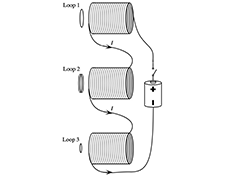
Students begin the tutorial by considering two conducting loops of the same radius held near a solenoid. The loops are the same distance from the end of the solenoid and from the axis of the solenoid, but have different resistance. Through discussion with one another and with staff, students come to recognize that the emf in a loop depends on the change in the magnetic flux through the surface of the loop. They are led to recognize that the current through a loop depends on the material from which the loop is made, while the emf induced does not. Students are then given a statement of Faraday’s law and use this to revisit the pretest questions.
In the second section of the tutorial students consider three applications of Faraday’s law. They examine a simple galvanometer and account for how it can be used to detect current. They then make a simple electric motor and apply the ideas introduced in the first part of the tutorial to account for the motion of the coil of wire in the motor. [The motor consists of a coil of wire with leads stripped on one side only; a circuit connecting the coil to a battery (when the stripped sides of the leads are in contact with the supports); and a strong magnet.] Students are asked to describe the magnetic moment of the wire coil when current is flowing in the circuit, and to predict the direction in which the coil will spin as a result of the interaction with the strong magnet. They then predict the effect of reversing the leads to the battery or reversing the orientation of the strong magnet. As a final application, students consider how the motor can be used as an electric generator. They predict the direction of the current induced in the wire coil by the field due to the strong magnet when the wire coil is disconnected from the battery and gently rotated. Students use a micro-ammeter to check their prediction.
For instruction tips, login or register as a verified educator to see the Instructor Guide.
Prerequisites
Students will need to draw on the experience in several prior tutorials. They will need to be familiar with: the magnetic force on a moving charge, the magnetic field of a solenoid, the magnetic moment of a current loop, the interaction of magnetic objects, the flux through a surface, and induced current. It is expected that students will have been introduced to the concept of emf and how it relates to current and resistance.
Equipment
Special Instructions
To be constructed (as shown below)
- 6 galvanometers
- 6 electric motors
Galvanometer:

Galvanometer magnets should be about 3" long. Coils should have ~40 windings.
Motor/galvanometer

Motors coils should be ~4" in diameter with 4 windings of stiff wire. Each lead to the coil should be stripped of insulation for half of its circumference.
Generator coils should have about 16 windings of partially stripped wire.
List
- ammeter
Coming Soon! We hope to release the discussion section on each tutorial by the end of July 2024.
